3DScope II - Camera Position - Overview
Hardware Configuration
Table of Contents
The purpose of this article is to detailed information about how to calibrate and configure a 3DScope II people counter.
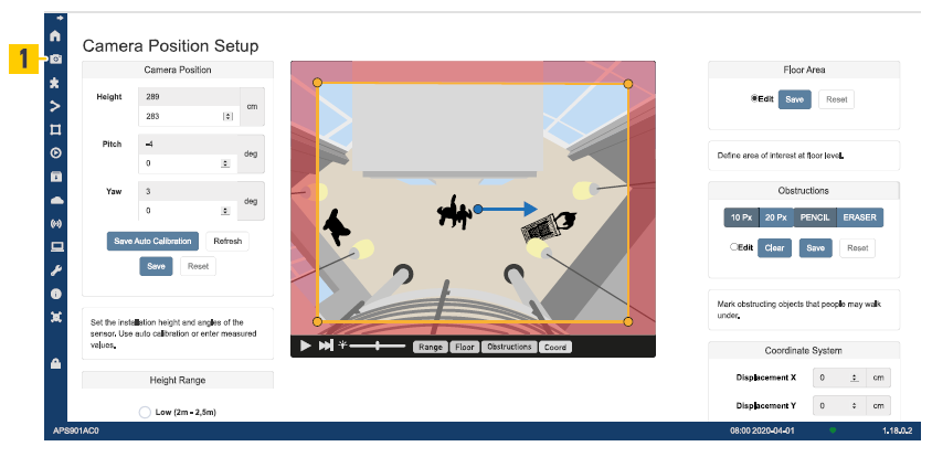
Camera Position Setup
The device has an inbuilt tilt measurement and can approximately measure its own. mounting height with an accuracy ~5%. These values are visible on top of the input fields. But they are not automatically used - to be human verified.
The height is the distance between the device level and the floor level.
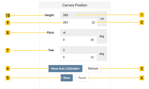
- The Refresh button is used obtain new measurements from the counter (Fig. 2 /3).
- Use Save Auto Calibration button to apply/save the auto-calculated measurements (Fig. 2 /6).
- (Optional) Input the values manually for the pitch (Fig. 2 /8) and yaw (Fig. 2 /7) angle or the height (Fig. 2 /10) by field (Fig. 2 /9) or using the spin control (Fig. 2 /2).
- Press the Reset button To go back to the last saved settings (Fig. 2 /4).
- To save and apply all the settings in the device click the Save button (Fig. 2 /5).
Height Range
 |
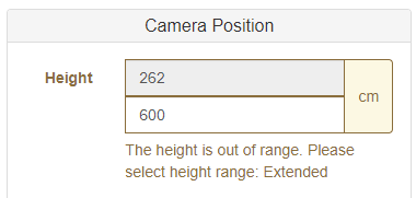 |
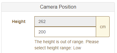
Is there is an "Out of Range" error indicated by the height detection, 1st try adjusting the height range of the device. Otherwise the counter may need to be physically moved higher or lower or possibly switched for a different model to support the installation requirements.
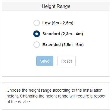
For more information related to the Height Range and coverage area - refer to the SMS Storetraffic — 3D Scope II-LC coverage chart
Floor Area
The floor area is used to define the area where people can be tracked and counted and cannot be placed where the RED out of range area is.
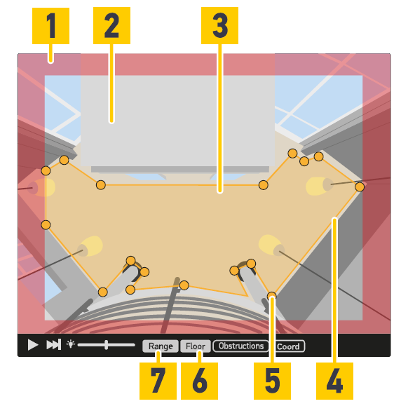 Figure 1
- To define the floor area (Fig. 1/3) in the live view activate the Edit button (Fig. 2/3) .
- To see the unusable area (Fig. 1/1) and usable area (Fig. 1/2) click the Range button (Fig. 1/7). The usable area is the range where people can be tracked and counted.
- To see the floor area (Fig. 1/3) defined by the yellow floor area polygon line (Fig. 1/4) click the Floor button (Fig. 1/6).
- Define the floor area by moving/adding/deleting points (Fig. 1/5). The floor area is defined by a minimum of 3 points and a maximum of 20 points.
- To go back to the last saved settings click the Reset button (Fig. 2/1).
- To save all the settings in the device click the Save button (Fig. 2/2).
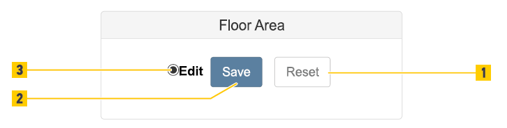 Figure 2
Obstructions
Ceiling panels, door compartments, exit signs or hanging objects that intrude into the monitored area of the device from the top can affect the counting accuracy. If People can stand below these objects, the objects must be masked to disregard them in count calculations.
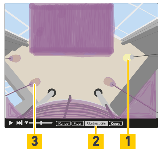 Figure 1
- To mark obstructed objects in the live view activate the Edit button (Fig. 2 /5).
- To see marked objects click the Obstructions button (Fig. 1/2).
- To draw or erase marks in the live view click Pencil or Eraser button (Fig. 2/1).
- To define the line width for drawing/erasing click 10 Px or 20 Px button (Fig. 2/6).
- To draw lines (Fig. 1/3) for marking objects (Fig. 1/1) click and hold mouse button in the live view.
- To go back to the last saved settings click the Reset button (Fig. 2/2).
- To save all the settings in the device click the Save button (Fig. 2/3).
- To erase all marks click the Clear button (Fig. 2/4).
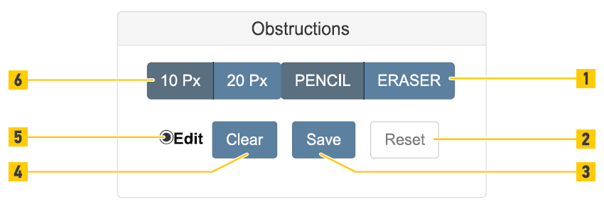 Figure 2
Coordinate System
This function is NOT currently used by SMS Storetraffic.com