3DScope II - Connection Diagram
Gain an overview of the connection diagram of 3DScope II, with diagrams illustrating all necessary connections.
Table of Contents
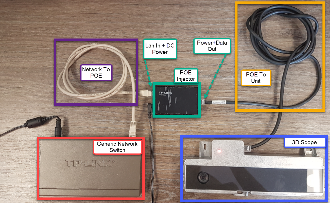
Below is an example of typical Wiring of a 3D Scope Unit
Simplified wiring model:
Confirm that network cable from the POE (Power+Data Out) is connected to the Unit
Confirm that network cable from the unit is connected to the POE Injector (Lan IN)
Confirm that the POE injector is powered on and has a green light
Confirm that POE Injector to the switch is connected
Confirm that the network onsite is working (customer responsibility)
* If the customer is using POE Switches, this step is supported by the customer and SMS cannot help determining if the switch POE is functional or not.