3DScope II - Customer Device Calibration
How to calibrate the counter
Table of Contents
Overview
The scope of this article is explain how to perform an initial calibration on a newly installed traffic counter. Installation and network programming is covered in other articles.
This article provides information for the optimal configuration of the 3DScope II people counter. Personnel must carefully read and fully understand this manual before performing any configuration tasks.
Requirements to calibrate the 3DScope II counter
- Must be able to access the traffic counter through the web browser.
- Device has been installed in a suitable unobstructed location over the desired monitoring area.
- Knowledge of user name and password to login to the counter.
Device Calibration
Calibration consists of the following tasks
- Verifying the Entrance View from the counter
- Setting the floor area in the counter
- Setting the count lines in the counter
- Verifying the device PUSH communication settings
- Assigning the device to the software.
-
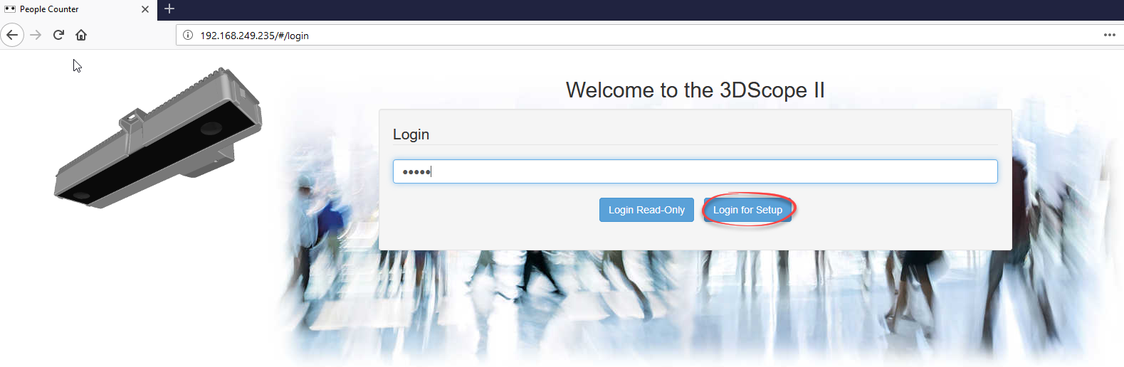
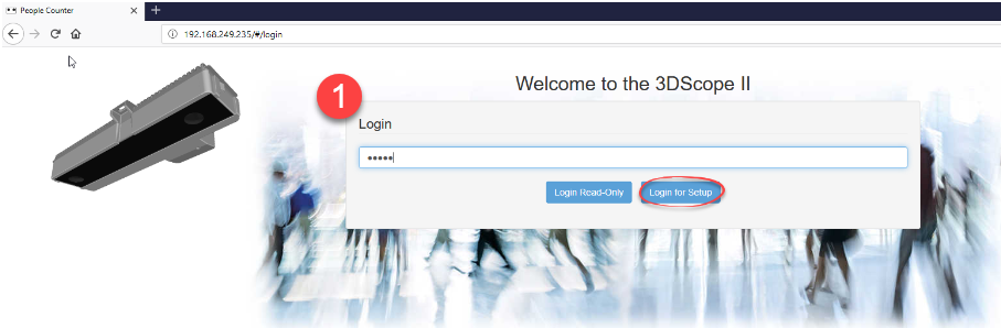
Login to the 3DScope using it's IP address in the browser. Default password: admin (Do Not Press Enter, but Click Login)
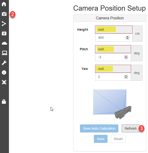
- Select Camera Position from left side menu.
-
Click Refresh - For Auto Calculation of mounting height.
-
Click Save Auto Calibration - To Apply Auto-Calculations of Height/Pitch and Yaw
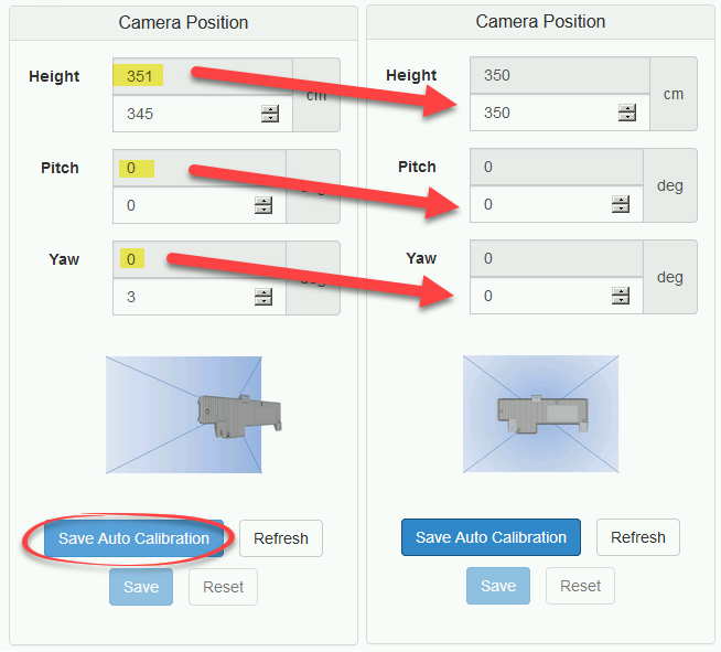
- See troubleshooting section in the event that Auto-Calculations of Height / Pitch and Yaw are not returned or state "undefined".
- See troubleshooting section in the event that Auto-Calculations of Height / Pitch and Yaw are not returned or state "undefined".
-
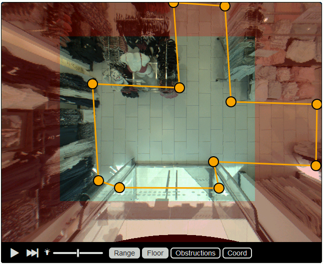
Verify that the counter is positioned correctly to cover the entrance. The entrance should appear in the Clear part of the image and NOT in the red out of bounds area.
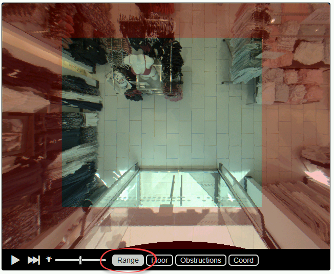
- Make Sure Range is Enabled
- Customer Entrance or desired counting area MUST be in the clear. Refer to troubleshooting section for process if entrance is NOT in the clear.
-
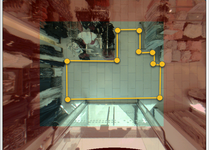
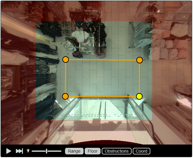
Set the Floor Area
- Drag the yellow points to define the monitored floor area, double click on line or dots to add/remove additional points as needed.
-
Place Yellow points on the floor and NOT on any permanent vertical structures and remaining inside the Range.
- Incorrect Placement
-
Correct Placement
- Incorrect Placement
-
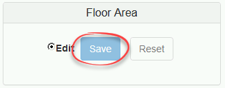
Save Floor Area
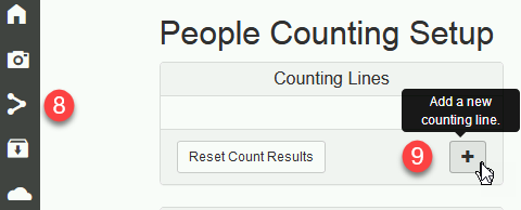
- Select Counting from Left Side Menu
-
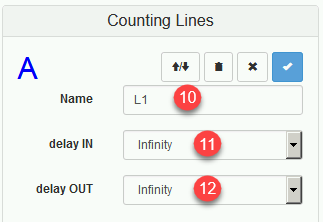
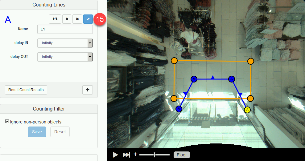
Click the + icon
- Input L1 for the count line name
- Select Infinity for Delay IN
-
Select Infinity for Delay OUT
-
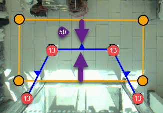
Drag the Count Line points to define the counting zones (double click on line or dots to add/remove additional points as needed).
- The count line needs to be defined within the Floor Area (Yellow Box), however the end points of the count line should be outside of the Floor Area Box
- The count line should divide the Floor Area into 2 areas which are considered the IN initialization area and the OUT initialization area. There must be a minimum of 2 feet, 24" or 50cm within each zone per direction inorder to properly pickup a target.
-
Toggle IN/OUT direction arrows so that the arrows represent the IN direction into the location or desired counting area.
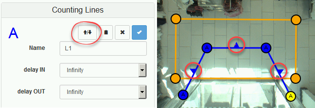
-
Click the check mark to Save Changes
-
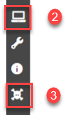
Select Diagnostics
-
Select "Mark Objects"to visualize when someone is detected by the counter.
- Adults appear as Red
- Children appear as Yellow
- Objects appear as Grey
- Carts appear as Blue
- Click Play Icon to start live video stream.
-
Request customer to perform a walk test of the calibration to determine if device is counting properly. Reset Count Results as needed.
- Walk Straight IN/OUT - Results in Counts
- Walk Left and Right Extremes - Results in Counts
- Walk Across Entrance inside location - Results in NO Counts
-
Walk Outside Entrance - Results in NO Counts
- If the above fails refer to troubleshooting section
- If Walk Test is successful, calibration is complete. Proceed to obtain the following deliverables.
- Screenshot of calibration
- Backup File of Camera settings
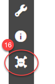
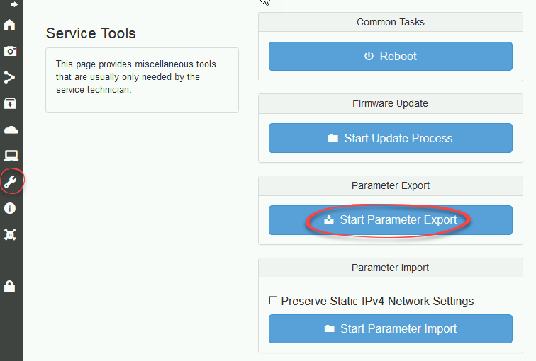
- Select Service Tools
-
Select Start Parameter Export
-
Save File and indicate name of customer, location and leave MAC address in file name.
-
Set Time Zone
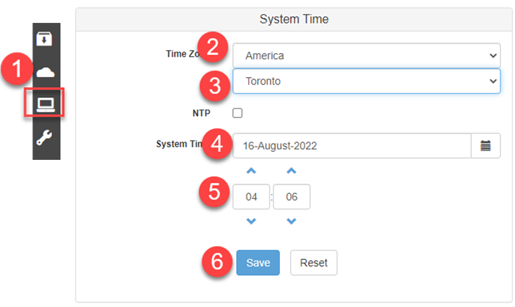
1.Click on “Other Settings” icon, on the left side
2.Select your device’s Region
3.Select a city in the same time zone as your device
4.Select today’s date
5.Input in the actual time (24-hour clock, i.e. 1pm = 13:00)
6.Click “Save” -
Reboot Camera
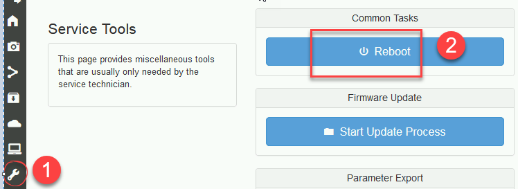
1. Click on "Service Tools"
2. Click "Reboot"
23. Verify that settings are correctly saved
|
1. Log back into camera 2. Click on "Other Settings" to ensure that time zone and time are correct. 3. Click on "Diagnostics" to ensure that counting zone and counting line are correctly saved. |
FAQ
Where do I book a calibration?
The links below are for the initial calibration, which is included free of charge with the purchase of a new device:
3DScope II - Calibration (Pre-Paid) - MAX 3 Devices
3DScope II - Calibration (Pre-Paid) - 4 to 6 Devices MAX.
Where do I book a paid calibration?
Use the link below if your device has already been calibrated and has since been relocated or repurposed at a new location. In this case, recalibration fees apply:
3DScope II - Calibration - PER DEVICE - Fees Apply