3DScope II Multi-Sensor Fusion for Improved Data Accuracy and Insights
Enhance multi-sensor fusion with 3DScope II for greater data accuracy and real-time decision-making
Table of Contents
Overview
This article will provide the planning, deployment and configuration process to implementing a successful counting array of 3DScope II counters in a network to cover a wide area where a single device would not be able.
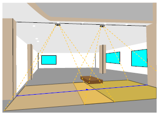
With the Multi Sensor Fusion it is possible to combine up to 10 sensors. With this fusion a wide entrance could be covered with multiple sensors and used by fusion to a master sensor with only one wide counting line. The master gets all the tracking information of the other sensors to count and to hide U-Turns. All the interfaces as Data Recording, Push Services or REST the master interacts as one master interface.
The maximum monitored area can be extended from 8 m x 8 m (26.2 ft x 26. ft) with 1 device up to 8 m x 22.8 m (26.2 ft x 74.7 ft) with 2 devices and so on.
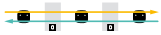
Example of Sensor fusion to cover a wide entrance
Requirements
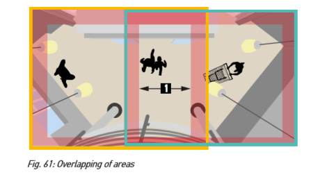
- It is important that the monitored areas of the individual devices overlap by at least 100cm or 3.3ft (Fig 61/1)
- DNS Service Discovery is available in the network
- All devices have activated DNS-SD and SSH
Planning the Installation of Multi Sensor Fusion counters
- Obtain the width of all entrances and area to be covered
- Obtain the height of each location where a 3DScope II will be mounted.
- Determine the coverage are of each counter based on the mounting height using the coverage area reference chart
- Plan to align the counters so that there is a minimum of 3 feet ( 1 Meter) of overlapping coverage in the desired monitoring area
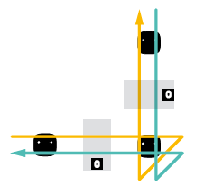
- Cameras do not need to be mounted pointing in the same direction, however it will make the configuration simpler if the coverage allows for it.
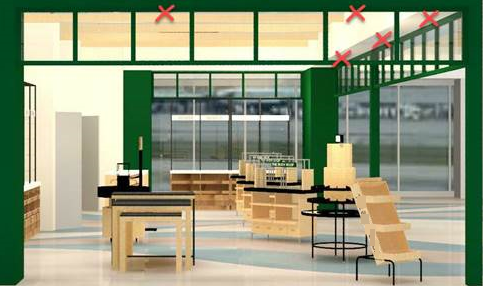
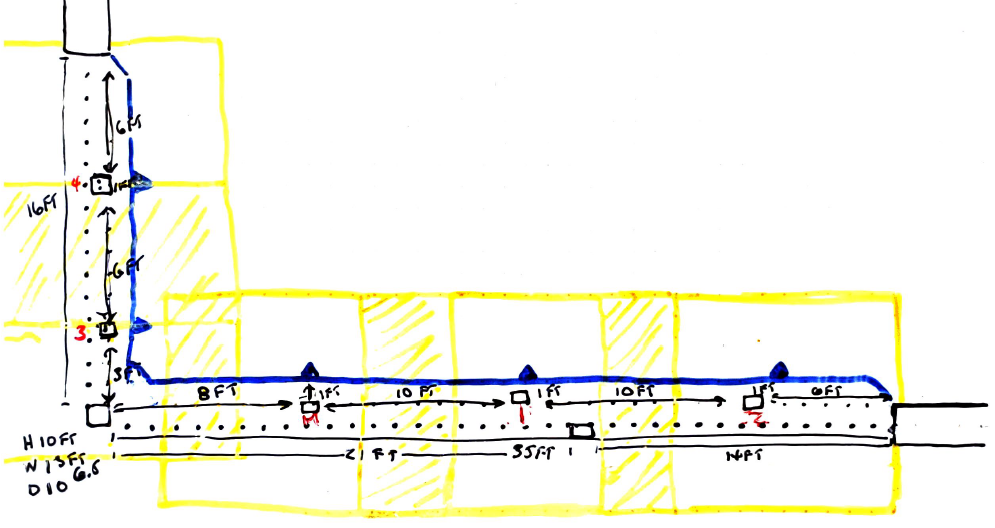
Example of Plan
How to configure multi sensor fusion
Perform on all counters of the array
- Program all counters to be used in the fusion array for the same subnet, each device will need to communicate with the master unit.
- Configure the Camera position of each device (Height, Pitch, Yaw or Auto Calibrate and set Floor Area (Yellow box))
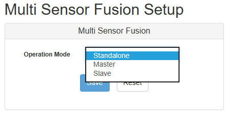
-
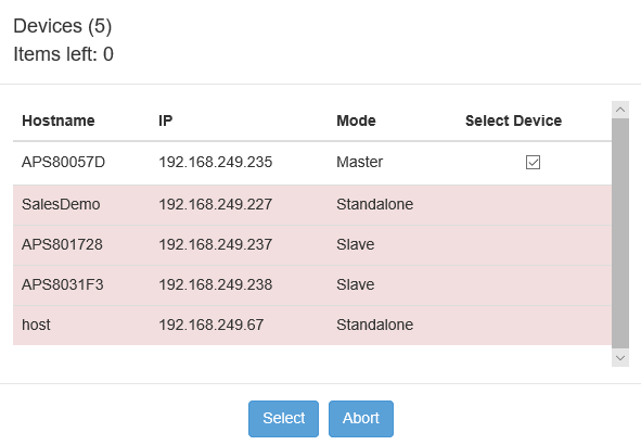
Select operational mode for each device (1 Master and the rest Slaves (For each array), independent counters stay on Standalone)
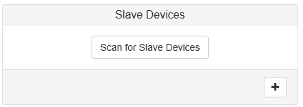
-
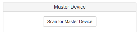
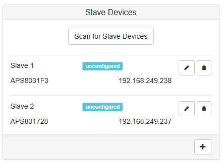
Scan for Slaves on Master
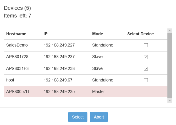
-
Check off to add slaves for communication to Master
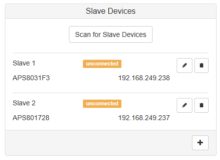
-
Verify that slaves is now appearing on Master counter
-
Scan for Master on Slave counters
-
Check off to add Master for communication to Slaves
- Verify that master is now appearing on slave counters
-
Configure the array from the Master
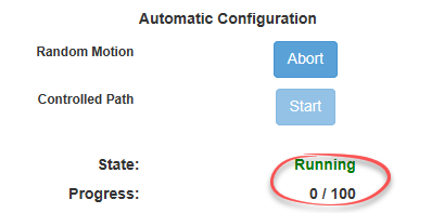
- Use Random Motion for when there is a lot of activity in a location which prevents using a controlled walking test.
- Use Controlled Path for when there is very little traffic someone will need to walk under counters as follows.
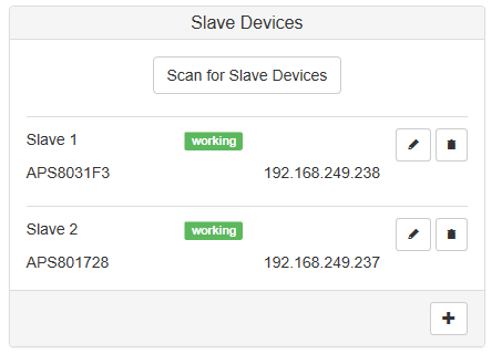
- A progression bar will appear which considers all counters in an array. When 100% is achieved all counters status should change from unconfigured to configured. When all counters are configured, they should be updated with the status of working
- A progression bar will appear which considers all counters in an array. When 100% is achieved all counters status should change from unconfigured to configured. When all counters are configured, they should be updated with the status of working
-
Once the automatic configuration has been completed and each device displays working
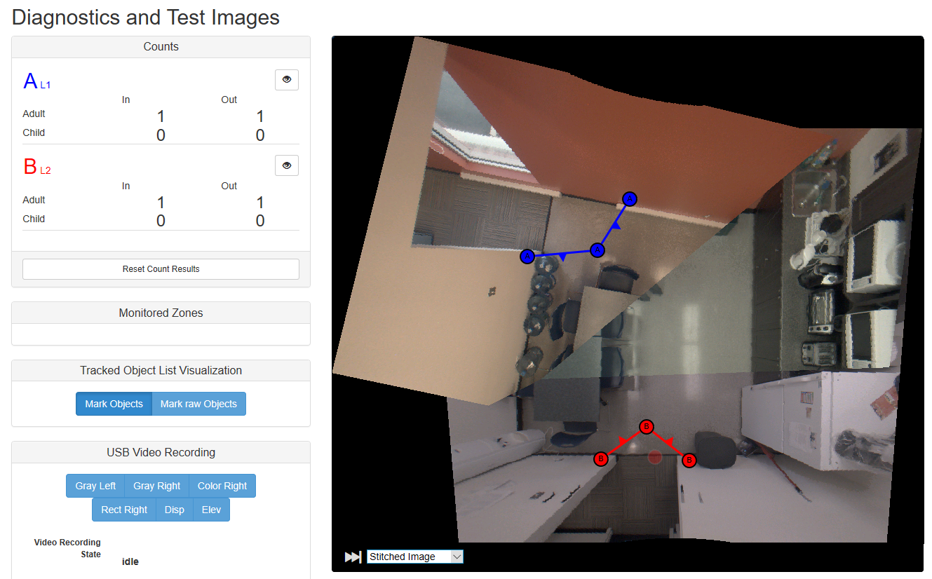
 proceed to set the count lines on the Master device as you would for a stand alone device. You will notice that the view has been updated with a stiched image from all the counters with the stiched image.
- Walk Test using diagnostics with marked objects only as video streaming is not availible.
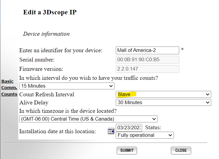
Entering the devices in T.M.A.S. Equipment Inventory
Be sure to designate the slave units as "Slave" in the Count Refresh Interval field and click submit.
 |
F.A.Q.
Q: How many 3DScope II counters can be used together in fusion mode to cover a wide area?
A: Up to 10 counters as of firmware version 1.14
Q: How much overlap is required to setup 2 or more counters in multi-fusion?
A: 3.3 feet (1 meter) with each adjacent device.
Q: Can the master return a "combined" video?
A: No, since the counters can be installed at different heights, pitch and yaw - the resulting combined video would not be (or highly likely be) plausible for a user to understand/use the resulting video. Each counter does however return its own video still.
Q: Can you mix Type E and Non Type E counters? (Type E are newer counters as the result of an internal memory chip change, counters typically purchased in 2018 or later).
A: Yes they can be mixed without issue.