3D Scope II - LC / HC coverage chart
How wide an area can a device cover
Table of Contents
Overview
This article provides measurement information to determine the coverage area for a 3D Scope II counter depending on the device mounting height.
It is a complement to our installation article: Installation of a 3D Scope II Traffic Counter
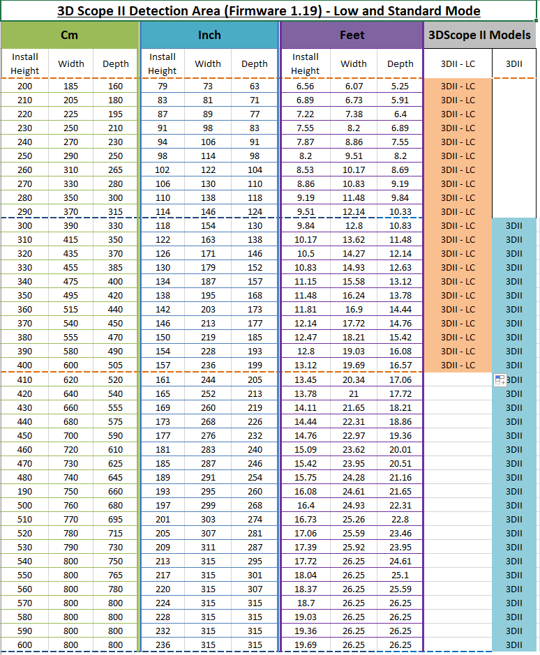
LOW AND STANDARD MODE - Detection Area for 3DScope II LC and 3D II (High Ceiling)
IF using Staff Exclusion Kits
The installation of the 3DScope II LC or HC model height may NOT exceed 4m / 13ft
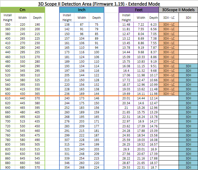
EXTENDED MODE - Detection Area for 3DScope II LC and 3D II (High Ceiling)
How is it used?
- Determine the Installation Height: Measure the height from the floor to the ceiling or wall bracket of where the counter is to be installed. Installation is Ideally centered to the entrance and 2 feet into the location where the counter view would be free of obstructions.
- Reference: the above detection area charts to determine the coverage Width and device model rounding down from your measurement from step. Green Box area for LC model or Blue Box for Regular Model.
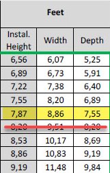
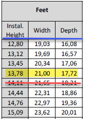
| Chart Use Example: | |
|
Installation Height of 8 feet
|
Installation Height of 14 feet
|
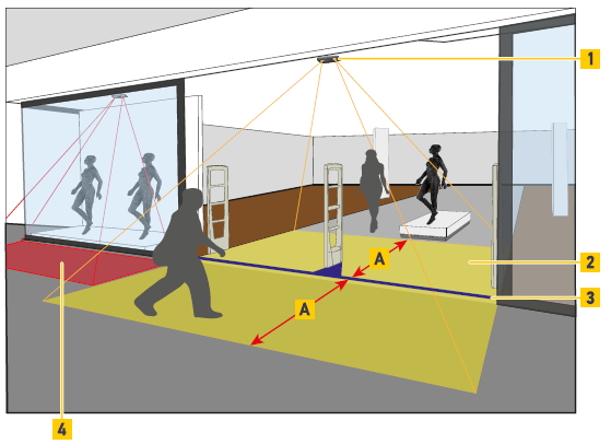
| A | Coverage Area |
| 1 | Mounting Position |
| 2 | Monitored Area |
| 3 | Count Line |
| 4 | Area covered by 3DScope in Pass-by Mode using a mounting angle |
When Counter Coverage Buffer is Required
NOT REQUIRED |
REQUIRED |
|---|---|
 |
 |
|
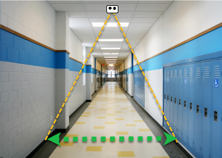
A corridor-type entrance (where sharp-angle entrances or exits are not possible) : The coverage chart can be followed as-is. |
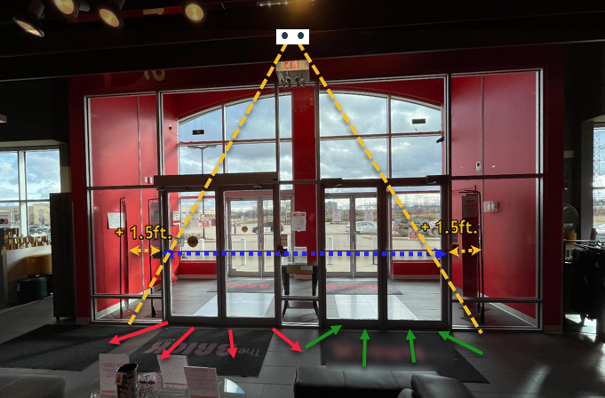
A wider entrance (where sharp entrances and exits are possible) : In order to ensure good coverage, SMS recommends a minimum of 1.5ft (50cm) of additional width to be added on EACH SIDE OF THE ENTRANCE, when calculating mounting height. |
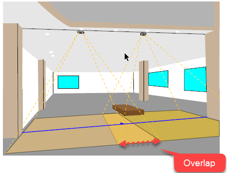
Using Multiple Devices (Multi-Fusion) to cover a large area
When the installation height does not allow for a single device to cover a wide area or the area is simply beyond the max capability of a single device, multiple devices (Up to 10) connected to the same network can be used to cover a single area.
When calculating the coverage area for multiple devices, there must be at least 3.3 feet (1 meter) of overlap to allow for the proper initialization of people between counters.
The maximum monitored area can be extended from 8 m x 8 m
(26.2 ft x 26. ft) with 1 device up to 8 m x 22.8 m (26.2 ft x 74.7 ft)
with 2 devices and so on.
| Fusion of 2 Devices | Fusion of 4 Devices |
 |
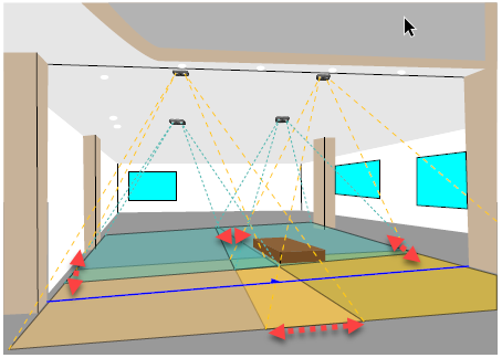 |
3DScope II Coverage when mounted at an angle
Warning
Mounting the counter at an angle may slightly reduce the counting accuracy due to the following scenario:
A larger person close to the camera obstructs the view of a person behind, resulting in the person behind not being counted or filtered out.
- The device can be angled up to 45 degrees (in optimal environment) with the use of an SMS supplied mounting bracket.
- Counters are typically mounted at angles for the following reasons
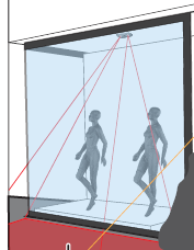
- When using a 3D II for capturing pass-by traffic through a display window.
- When using a 3D II in creative uses such as corners, kiosks or
- (Store-in-Store).
- Ceiling is sloped
- There are too many obstructions to install centered to the entrance, or a bit off-center and a level ceiling surface is NOT available.
- Cannot be installed approximately 2 feet where the depth of the coverage area will NOT meet the base of the entrance.
- Where there is NO ceiling or ideal mountable surface area close to the entrance or area of interest.
Refer to the following attached worksheet to plot the angle of measurement to determine the displaced coverage area.
3D-Scope Monitoring-Area calculator.xlsm
Using the angle calculator
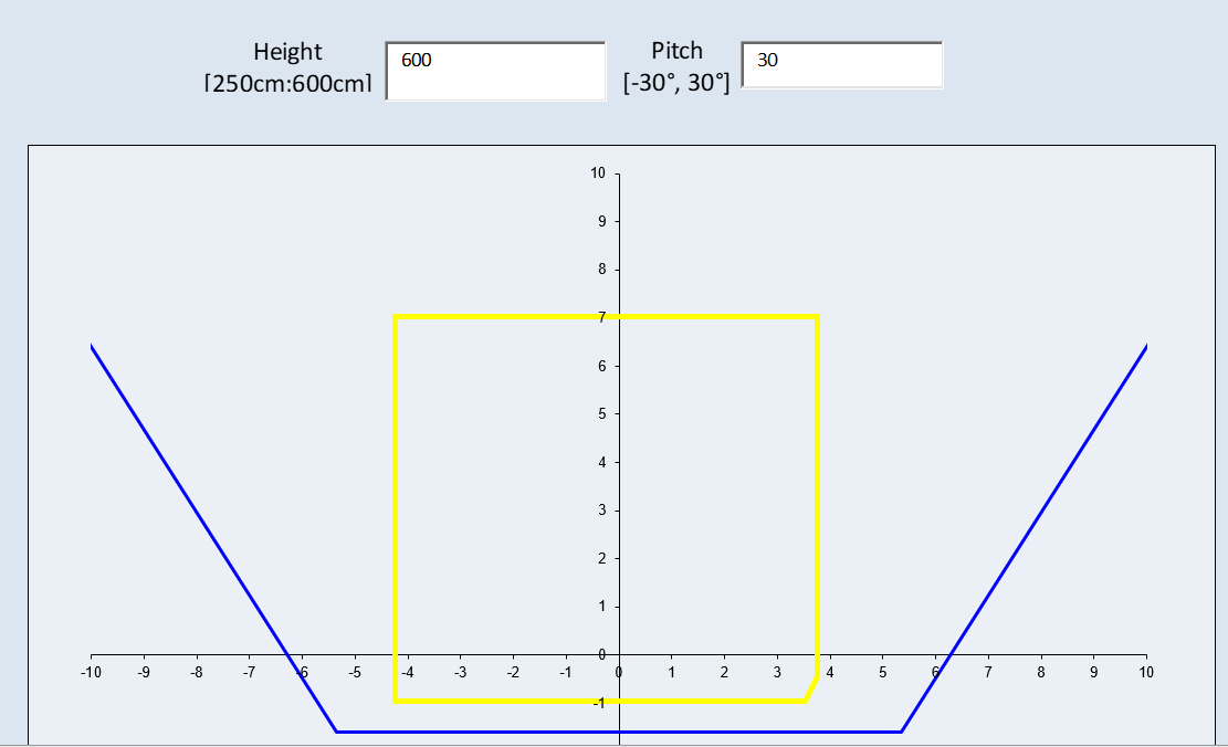
- Download the above worksheet calculator
- Input the installation height
- Input the Angle (Worksheet max is 30 degrees) 3DScope II can go up to 45 degrees, however between 30 to 45 degrees the coverage is best viewed through the device during installation
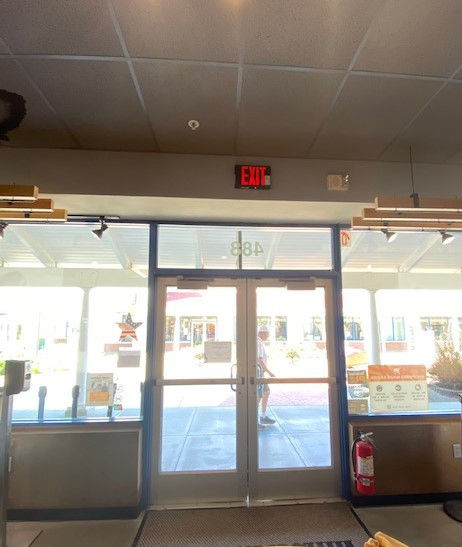
For additional assistance with mounting, please email support or contact us through the chat icon at the bottom-right of the screen or found within the T.M.A.S. application.
Be sure to provide photos of entrance, including measurements entrance width and ceiling height.
Examples:
 |
 |
FAQ
Q: Does the coverage chart apply to both the indoor and outdoor models of the 3D Scope II?
A: Yes, the coverage chart applies to both indoor and outdoor versions of the 3D Scope II.
However, please note that the High Ceiling (HC) model is not available for outdoor use.
For outdoor installations, only the Low Ceiling (LC) model is sold by by SMS.