Installation of the 3D SCOPE II - Outdoor
Outdoor Installation Instructions for the 3D SCOPE II Traffic Counter
Table of Contents
Overview
This article describes the Installation process to mount 3DScope II - Outdoor traffic counters. As well as lists the tools, equipment and steps required to complete successfully..
Tools Required
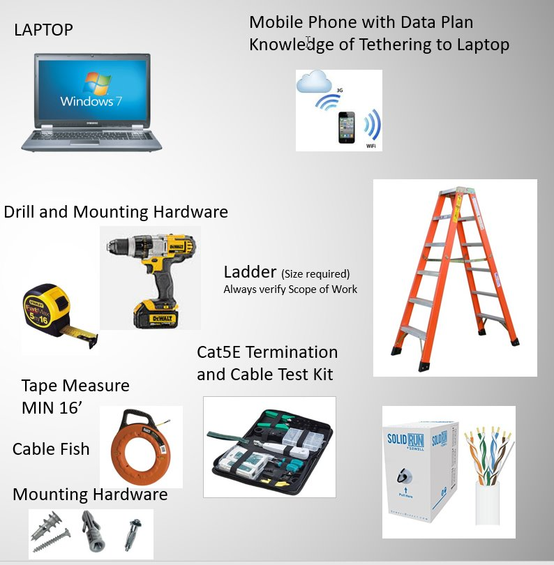
Note* Mobile Phone with Data plan is ONLY required in the event that remote calibration of the traffic counter is required, where the local network within the location is unable to provide internet access. For ceiling exceed height of 16 feet, or ruled unsafe for ladder use, may require a lift/skyjack.
Hardware
| 3d Scope II - Outdoor |
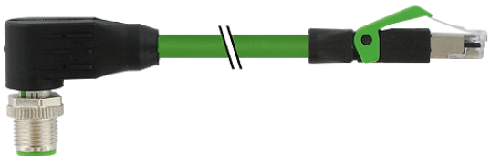
Ethernet connection cable M12 - RJ45 2M Length |
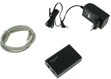
Outdoor Installation Kit | PoE Injector |
 |
 |
 |
 |
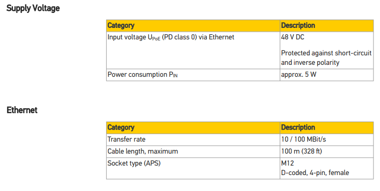
Technical / Mechanical Data
Electrical Data
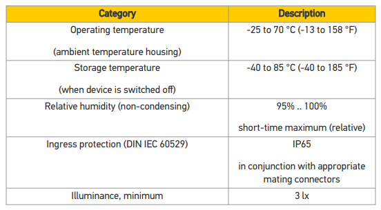
Environmental Conditions
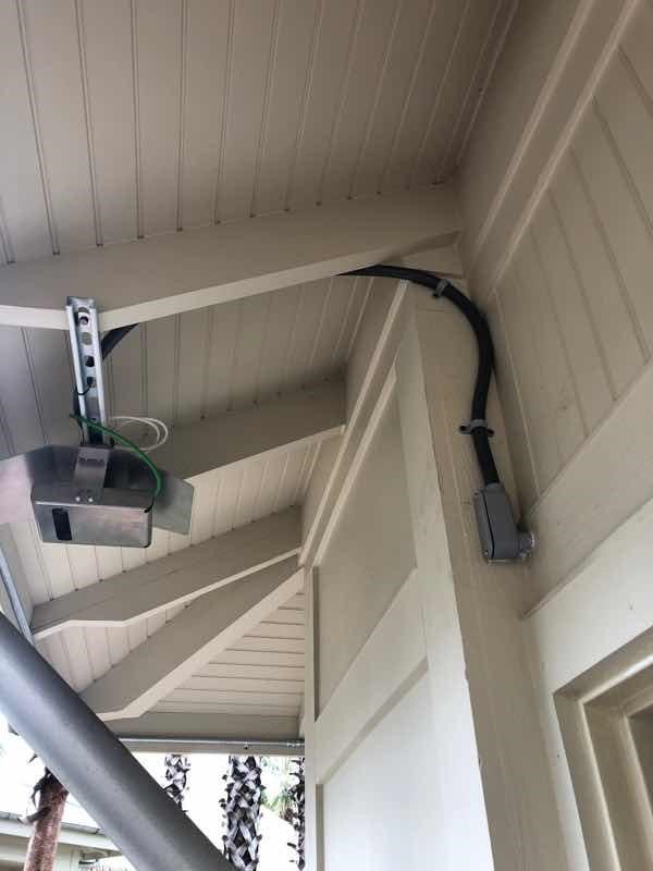
Installation Examples
 |
 |
 |
 |
Installation Scope of Work
- Determine the mounting location for the counter.
- Measure Height and Width of Entrance to be monitored.
- Verify the detection are to determine if the coverage will be desirable.
- Run the cable (more cabling info and guidelines here)
- Mount the traffic counter
- Install PoE Injector (Not required if there is an available PoE switch in this location with a free network port)
- Verify that 3D scope is online and communicating with T.M.A.S.
- Book the calibration session with SMS Storetraffic - Booking Link
Mounting Considerations
-
View of the counter MUST NOT be blinded or obstructed by the following.
- Entrance sign
- Hanging lights
- Signage
- Walls, Soffit, Glass or screens.
- Light reflective surfaces which may project light directly into the counter lens.
- Required illuminance: 3 LX
- Balloons or patio umbrellas
- Plants / Trees
-
Entrance Type
-
Door swings
- The counter will need to be located minimum 1 foot away from the monitored area than the MAX length of the door when fully swang.
-
Stairs
- NOT recommended - Installation over the actual stair steps
- Recommended - installation over the landing at the bottom or top of the stairs.
-
Door swings
Measuring the entrance and verifying the coverage area
Refer to the following articles for more information: 3DScope II - LC / HC Coverage Chart
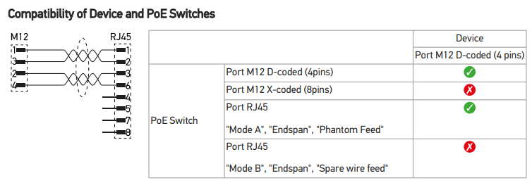
Connection topology and cabling for the counter
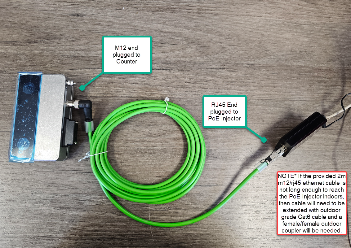 |
NoteThe provided M12 to RJ45 cable is only 2 meters in length, there for if this is not enough to sufficiently cable to indoors, an exterior Cat5/6 cable will need to be sourced and run and a weather resistant union female RJ54 to female RJ45 will also need to be sourced and used to connect the supplied cable to the run. See below. |
 |
Waterproof RJ45 Coupler Example: |
 |
Outdoor Ethernet Cable Example: |
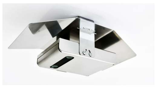
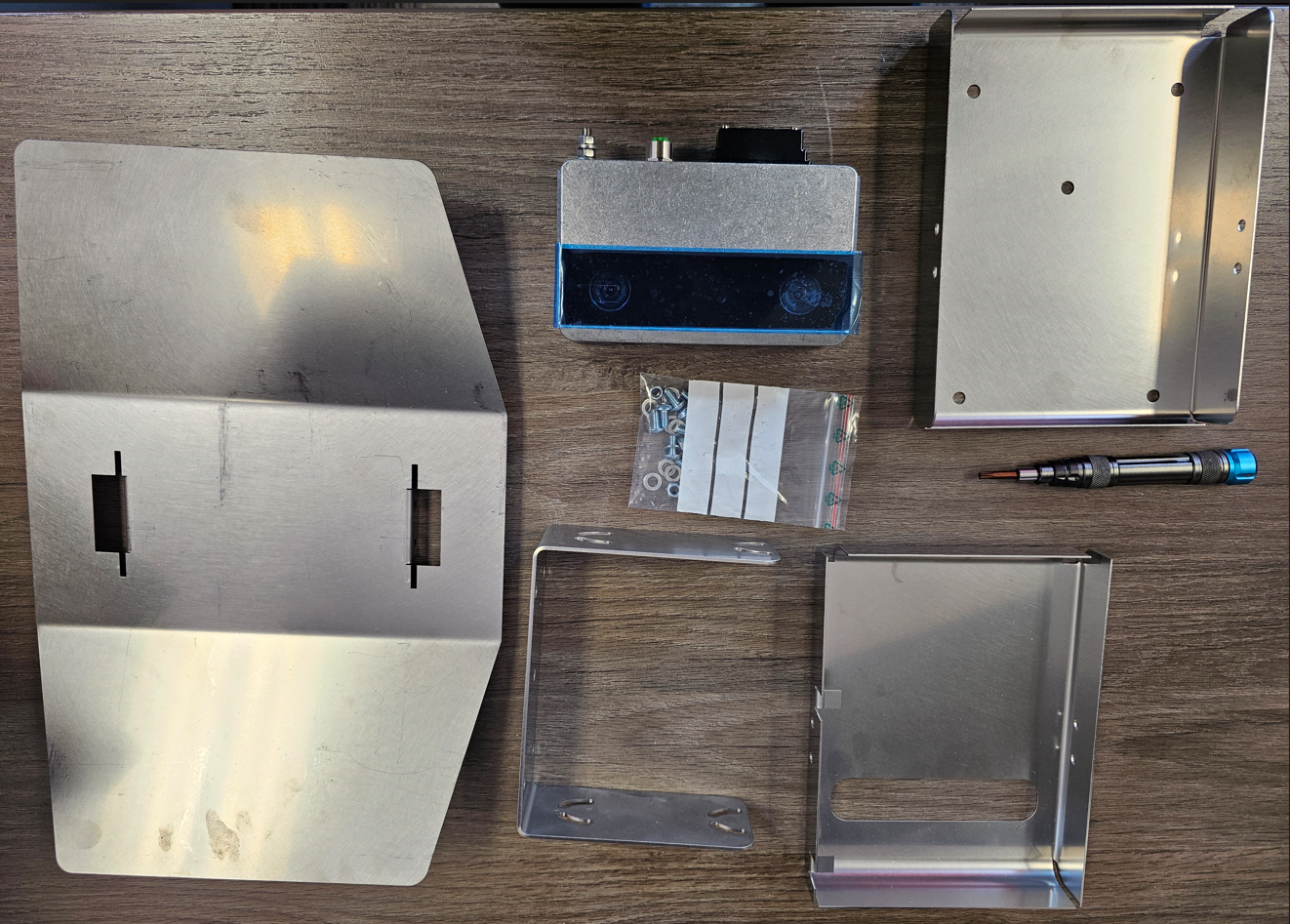
Mounting the Counter / Bracket
 | |
|
Equipment List - Included
|
Additional NOT - Included
|
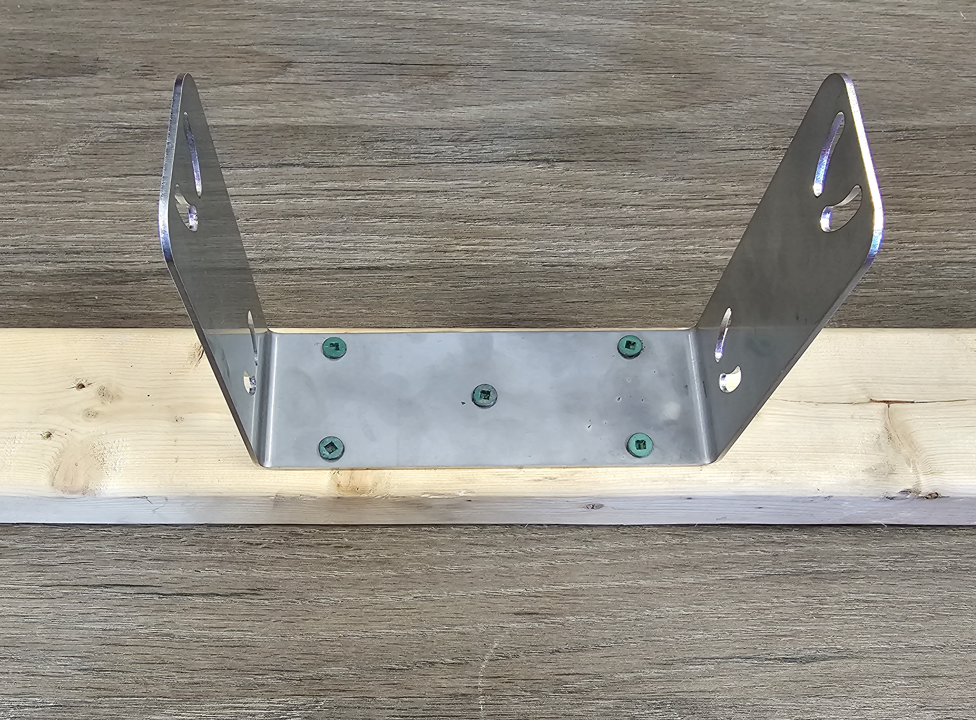 |
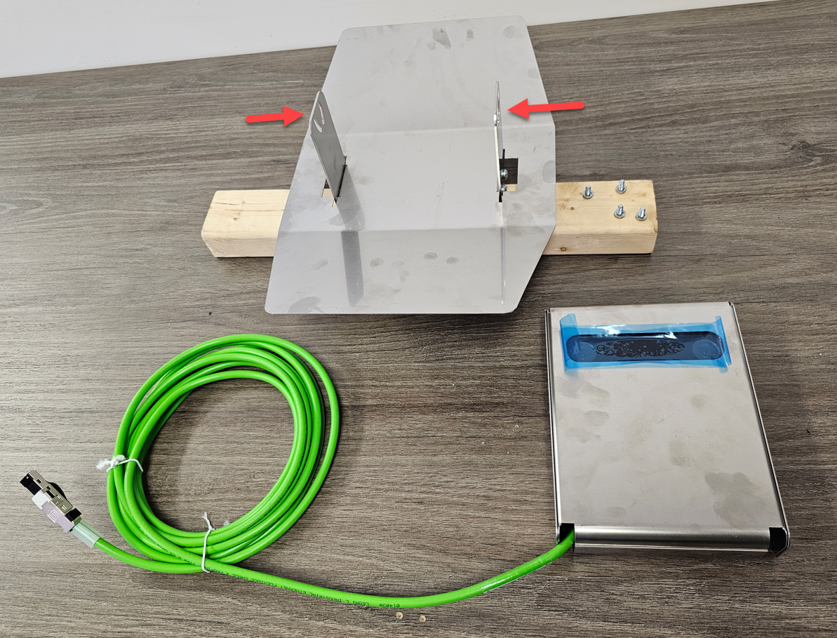
1. Securely attach bracket to mounting location. (Note*: Mounting screw hardware NOT provided) |
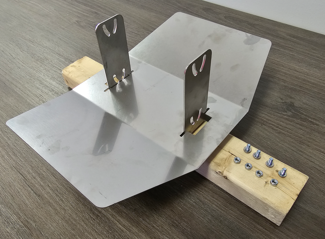 |
2. Counter weather cover will slide on bracket and be secured with provided mounting hardware (4x screws, washers and nuts). |
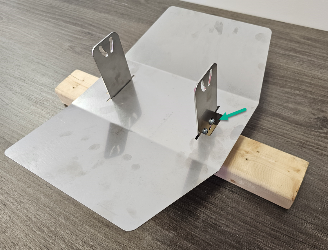 |
3. Attach weather cover (angle can be adjusted later).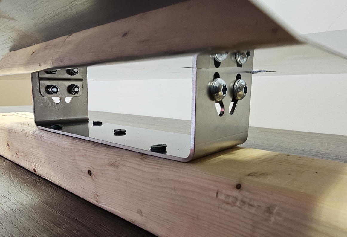
|
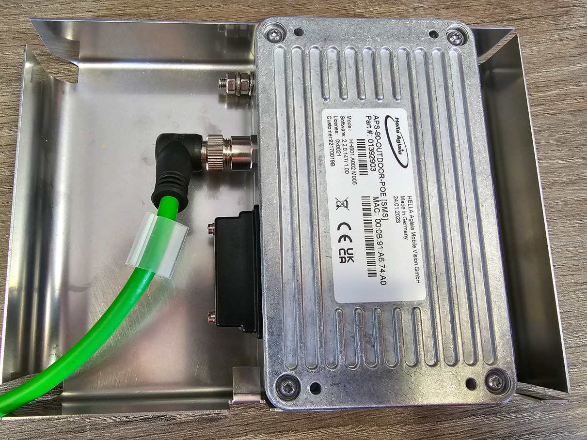 |
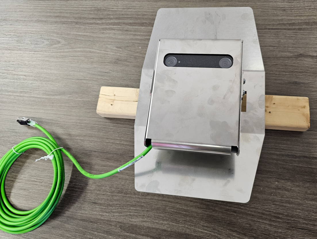
4. Connect the M12 end of the provided outdoor ethernet cablet to the 3DScope II - Outdoor counter and place inside the casing so that the holes on the sides aligned and feed the cable out the corner.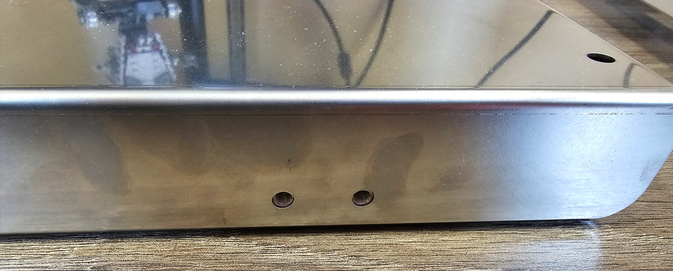
|
 |
5. Attach the incased counter to the bracket with provided screws and remove the lens cover.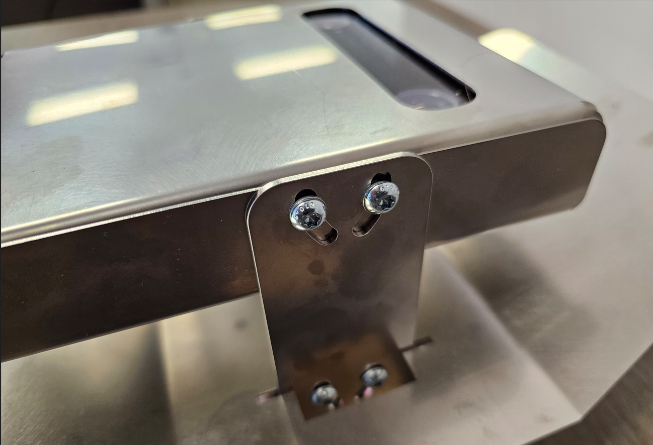
|
 |
6. Once counter is secured to the mount, the counter can be easily angled as needed during calibration.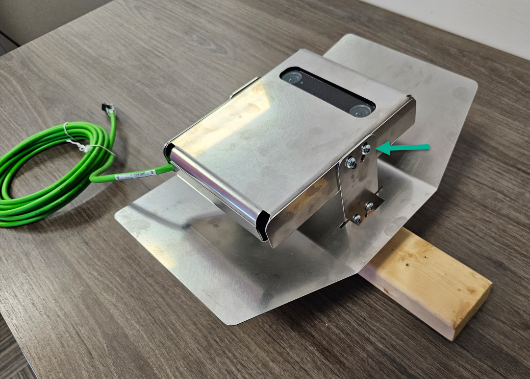
|
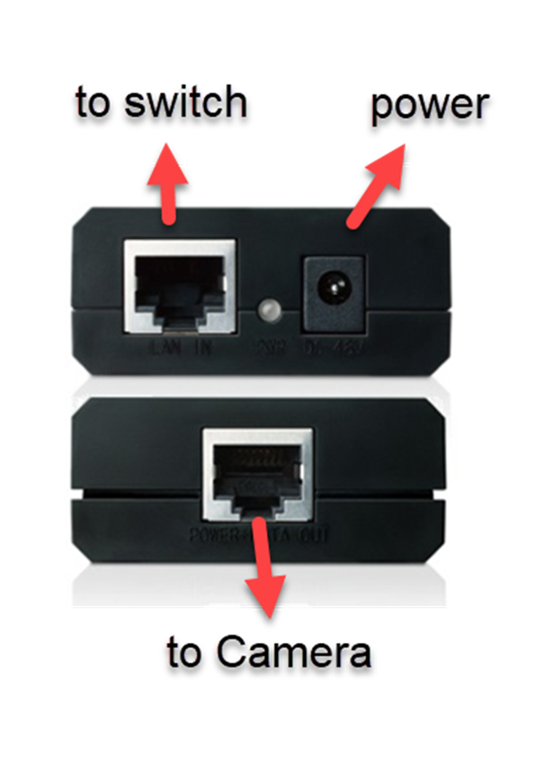
Installation of the PoE Injector (Recommended)
|
 |
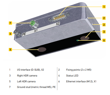
Status LED
Starting the device takes about 40 seconds. During this time the status LED is as follows:
- When the device starts the LED is illuminated in red for approximately 5 sec.
When the device starts the LED is illuminated in red for approximately 10 sec.
- During the rest of the startup process the LED flashes green.
- While waiting for DHCP the LED is blinking in yellow. This overlays the green blinking of startup process.
- At end of startup the LED is illuminated in green for approximately 6 sec. Then will remain on SOLID.
User interface is accessible approximately 10 sec later (approximate 2min from power on).
Verify that 3D scope is online and communicating with T.M.A.S.
This article explains how technicians can verify that a 3D Camera is online and communicating with the T.M.A.S. server, prior to leaving site.
FAQ
Q: I need an HC (High Ceiling) model for outdoor use. Is this available?
A: SMS only offers an LC model for outdoor use.
Q: What kind of lighting is best for the 3D Scope?
A: The minimum amount of lighting possible is 3 LUX, however, SMS recommends a minimum of 6 LUX lighting.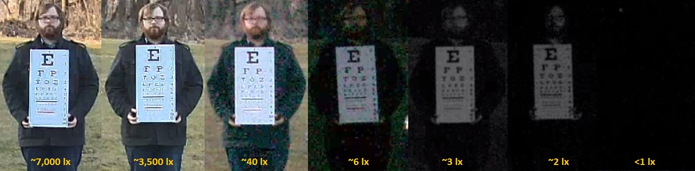
Q: Where can I find a mounting bracket for Outdoor Cameras?
A: Although not sold by Amazon, SMS customers have used the following models:
Universal Wall Mounting Bracket
L-Shape Dome Camera Bracket